Powerline Model 23-11
120 Amps
Date Code: MAY-22-03
Serial No.: A11040
Purchased: 7/03
Spare alternator
Powerline Model 23-11
120 Amps
Date Code: 60297
Serial No.: A06856
14 pole alternator puts out a 50% duty cycle on the R terminal (white wire) Ś 7 pulses per revolution (tach takeoff not used on Willow)
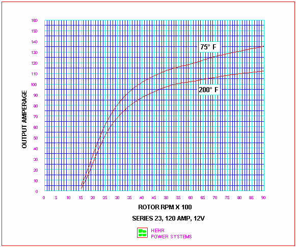
The alternator ratings are based on SAE standards Ś 6,000 RPM alternator speed and 78░F temperature. The maximum temperature is 300░F. The efficiency of a high-output alternator is around 49%. An automotive alternator is only around 30% efficient (Rodney Knelly at Hehr)
Pulley is a Powerline Model No. 8-603, 2.2" diameter. Crank shaft pulley is
4.75" diameter. (2.16 ratio)
Belt is a Gates Green Stripe (notches on belt), No. 9412 (12.5/13mm x 1050mm) or NAPA 25-10455 (25 9412). On the belt is written 13A1040. The belt lifetime is between 300 and 400 hours. Replace every 300 hours.
To remove the pulley nut, an impact wrench (rented) is magic. The nut is 15/16". Without an impact wrench, use a 5/16" hex key inserted into the center of the shaft to lock it and then use a wrench on the nut. The nut should be tightened to around 50 ft-lbs.
Defender carries parts for Powerline
Recommended alternator filters from Powerline: Electrocube (800-516-1112) G2438 fluorescent light filter on the field, G2418-150 on the power output.
Repair kit 13-113 (list $110). Rebuild the alternator every 3,000 hours. If the boat is left standing in a salty environment, the alternator may not output a voltage. If so, sand the slip rings to get rid of corrosion, sand the brushes, and reassemble. The alternator does not have any type of over-temperature current fold-back internal to it.
Rebuilt old unit that failed after about 2,000 hours. The repair place said that the bearings overheated due to too tight of a belt. They suggested tightening the belt just enough to stop the pulley from being able to turn when gripped with my hand. Then, run the engine until hot and adjust the belt again. The old unit is now a spare onboard.
.
Installed a low-pass LC filter from Newmar. Part number 150-A This filter is supposed to remove alternator noise from the radios.
| Name | Brand | Case Size | CCA | MCA | Amp-Hours | Reserve Cap. (min) | New |
|---|---|---|---|---|---|---|---|
| Starting Battery | Best 27MHC | Group 27 | 800 | 1,000 | 90 | 205 | 03/2023 |
| House (starboard settee Ś 4x 6V) | Trojan | T-105 | 225 | 447 | 03/2023 |
Battery cable between house batteries is 2/0 AWG Ancor.
| Size | Length | Width | Height | Weight* | Ah* | Stud |
|---|---|---|---|---|---|---|
| Group 27 | 12Š" | 7" | 10" | 60 | 90 | 3/8"(+) and 5/16"(-) |
| 4-D | 20Š" | 8Š" | 10╝" | 130 | 180 | |
| 8-D | 20Š" | 11" | 10╝" | 160 | 225 | |
| T-105 6V | 10Į" | 7╝" | 11╝" | 62 | 225 | 5/16" |
* Approximate, depending on battery technology, manufacturer, etc.
Reserve Capacity = minutes to drain 25 amps @ 80║F to 1.75V/cell (10.5V)
Amp-Hours = number of amps discharged for 20 hours @ 80║F to 1.75V/cell (10.5V). To calculate Amp-Hours capacity at a different discharge rate, use
CR = R * H * (CH / (R * H))P
where
CR Amp-Hour capacity at the new discharge rate H Hours that the capacity was specified at CH Amp-Hour capacity at the specified discharge rate R Discharge rate P Peukert's exponent (about 1.24 for flooded lead-acid, 1.12 for AGM)
Amp-Hours = (Reserve Minutes * 0.4237) + 14.5 (calculated from an Excel spreadsheet)
| % Charge | Specific Gravity |
Voltage (Open Circuit) |
Willow Ah Used |
|---|---|---|---|
| 100 | 1.277 | 12.73 | 0 |
| 90 | 1.258 | 12.62 | -43 |
| 80 | 1.238 | 12.50 | -85 |
| 70 | 1.217 | 12.37 | -128 |
| 60 | 1.195 | 12.24 | -170 |
| 50 | 1.172 | 12.10 | -213 |
| 40 | 1.148 | 11.96 | -255 |
| 30 | 1.124 | 11.81 | -298 |
| 20 | 1.098 | 11.66 | -340 |
| 10 | 1.073 | 11.51 | -383 |
from Trojan Battery User's Guide
| Device | Quantity | Type | Number Cells | Total Cells | Needed |
|---|---|---|---|---|---|
| Flashlight - Red Lamp | 1 | AAA* | 3 | 3 | 21 AAA |
| Flashlight - Rocky LED | 2 | AAA* | 3 | 6 | |
| Dinghy stern light | 1 | AAA* | 4 | 4 | |
| Headlamp (red/white) | 1 | AAA* | 2 | 2 | |
| Magnifying loupe | 1 | AAA* | 3 | 3 | |
| Thermometer | 3 | AAA* | 1 | 3 | |
| Penlight - Mag-Lite | 3 | AA* | 2 | 6 | 25 AA |
| Dinghy bow light | 1 | AA* | 4 | 4 | |
| Husky work light | 1 | AA* | 6 | 6 | |
| GPS - Garmin 76C | 1 | AA* | 2 | 2 | |
| FRS radios | 2 | AA* | 3 | 6 | |
| Weems & Plath Chronometer | 1 | AA* | 1 | 1 | |
| Flashlight - Dive light | 1 | C | 4 | 4 | 4 C |
| Flashlight - Mag-Lite, black | 3 | D | 2 | 6 | 6 D |
| Visor clip-on | 1 | CR2032 | 2 | 2 | 2 CR2032 |
| Digital calipers | 1 | LR44 | 1 | 1 | 1 LR44 |
* Rechargeable available
Rechargeable batteries onboard: Eneloop 28 AA, 20 AAA (new 2021)
Hellroaring Technologies, Inc. Model BIC-75150A S/N A01C3337 (5/01). This is wired to isolate the starting battery and the boat runs everything on the house battery. The starting battery is only used for starting the engine. Replaced the first unit that failed (internal MOSFET blown).
Blue Sea Systems 5511e e-Series battery switch dual circuit plus combiner. The switch is located in the battery compartment. To get to it, lift the starboard settee cushion and the switch is near the starter battery.
I designed and built my own electrical panel (2023) to replace the original
Bass Products, Inc. (out of business). The panel has a piano hinge at the
bottom, which allows me to quickly open the panel to get to all the wiring. The
new panel also has an
ELCI breaker to protect swimmers and others from leakage
currents.
Circuit Breakers: Carlingswitch AC/DC, Black Handle, #10 screw terminals
| Amps | Carlingswitch Part Number |
|---|---|
| 5 | AA1-B0-34-450-5D1-C |
| 10 | AA1-B0-34-610-5D1-C |
| 15 | AA1-B0-34-615-5D1-C |
| 20 | AA1-B0-34-620-5D1-C |
The following is the circuit breaker layout on the electrical panel:
| AC Breaker | Amps |
|---|---|
| ELCI/AC Main | 30 |
| Battery Charger | 15 |
| AC Outlets | 15 |
| Water Heater | 15 |
| Spare | 15 |
| DC Breaker | Amps |
|---|---|
| Cabin Lights | 15 |
| Accessory | 40 |
| Inverter | 40 |
| Fridge | 15 |
| Fresh Water Pump | 15 |
| Shower Sump Pump | 15 |
| Seawater Pump | 20 |
| Bilge Pump Upper | 15 |
| Bilge Pump Lower | 15 |
| Propane | 15 |
| Spare | 15 |
| DC Breaker | Amps |
|---|---|
| Radios & Radar | 40 |
| Instruments | 10 |
| Instrument Lights | 15 |
| Anchor Light | 5 |
| Running Lights | 15 |
| Steaming Light | 15 |
| Tricolor Light | 10 |
| Spreader Lights | 15 |
| Autopilot | 20 |
The Lectra/San circuit breaker (75 amps) is located in the engine compartment on the port side.
| ID | Type | Size | Comments |
|---|---|---|---|
| FB1-0 | ATC | 2A | Battery combiner ground |
| FB1-1 | ATC | 5A | Engine room light |
| FB1-2 | ATC | 2A | BATT1 sense to Link 2000 (blue wire) |
| FB1-3 | ATC | 30A | Battery Combiner A |
| FB1-4 | ATC | 5A | Upper bilge pump |
| FB1-6 | ATC | 5A | Lower bilge pump |
| ID | Type | Size | Comments |
|---|---|---|---|
| FB2-1 | ATC | 30A | Battery combiner C |
| FB2-2 | ATC | 2A | BATT2 sense to Link 2000 (violet wire) |
| ID | Type | Size | Comments |
|---|---|---|---|
| FB3-1 | ATC | 10A | Power to Ideal Regulator |
| FB3-2 | ATC | 2A | Ideal Regulator shunt protection |
| FB3-3 | ATC | 2A | Ideal Regulator shunt protection |
| FB3-4 | |||
| FB3-5 | |||
| FB3-6 |
| Location | Type | Size |
|---|---|---|
| SSB RT Head(1) | AGC | 5A |
| SSB RT Head(2) | AGC | 5A |
| SSB XCVR(1) | AGC | 30A |
| SSB XCVR(2) | AGC | 30A |
| SSB XCVR(3) | AGC | 5A |
| A/P FS1 | Auto | 30A |
| A/P FS2 | Auto | 5A |
| A/P FS3 | Auto | 5A |
| A/P FS4 | Auto | 5A |
| Lectra/San | MDL | 35A |
| Lectra/San | MDL | 30A |
| Lectra/San | MDL | 6╝A |
| Lectra/San | 5x20mm | 5A fast-acting |
| Furuno GPS | 5x20mm | 1A |
Installed behind electrical panel. From Yacht Corrosion Consultants (Professional Mariner) Zinc Saver: Installed 1999.
| Location | Manufacturer | Model No. | Lamp | Bulb/Base | Amps | Notes |
|---|---|---|---|---|---|---|
| Bow nav light | Aqua Signal | Series 40 | Imtra ILTW1157-SMW (LED) | T-8/BAY15D | 0.25 | 260 lumens |
| 25W 90002-7 (original) | 2.0 | |||||
| Stern nav light | Aqua Signal | Series 40 | HQRP G9-33SMD2835-3W (LED) | T-8/BAY15D | 0.25 | 310 lumens |
| 10W 90005-7 (original) | 0.83 | 150 lumens (?) | ||||
| Tachometer | Alla Lighting T10-3014-18R (2021) | W2.1x9.5d Mini Wedge | 0.16 | 220 lumens | ||
| IA62995 (1 or 2 candle-power, wedge base), GE 161 (original bulb) | 0.21 | 13 lumens | ||||
| Engine Gauges | Phinlion BA9S-2835-5SMD-R (red) | T-3╝/BA9S | 0.33 | |||
| 1893 (Dialight LED p/n 585-4213 ultra-red $6, LedLight p/n BF321CR3K-14V-P). | ||||||
| Can also use 756, 1813, 1889, or 1892 lamps (>13V). | ||||||
| Steaming Light | Perko | 964 DP CHR | SiriusLED CB 31mm | SV8.5 Festoon, 31mm length | 0.14 | 400 lumens |
| 71 DP CLR | 0.83 | 100 lumens | ||||
| Dome light - nav station | ABI | 7" | White: Sensibulb LED | G4 | 0.24 | 150 lumens |
| Red: G4-3014-48-LED | 95mA | 200 lumens | ||||
| Original White: 20W halogen | G4 | 1.67 | 300 lumens | |||
| Original Red: 10W halogen | 0.83 | 120 lumens | ||||
| Dome lightŚnear head | ?? | ?? | Replaced the white LEDs with LED strips of 2700K | 0.05 | ~90 lumens | |
| Spreader Deck Lights | ?? | ?? | GE 4411-1 35W 300 hours | 6.0 | ||
| Mizzen Deck Light | ?? | ?? | 1383 12V 20W R12 | BA15S | 1.67 | 160 lumens |
| Bonlux 1383 12V 4W (LED) | 0.33 | 300 lumens | ||||
| Cabin reading lights | Bass Products | 10-2222 (double swivel), 10-2162 (single swivel) |
90 94 (default) 1004 1142 |
G-6/BA15D | 0.58 1.02 0.94 1.44 |
6 CP, 75 lumens 15 CP, 188 lumens 15 CP, 190 lumens 21 CP, 264 lumens |
| PLT-300271 (LED) |
BA15D | 0.33 | 410 lumens, 2700K (Replaced all 6/2016) |
|||
| Chart light | Hella | 2AB 004 532-061 | Phinlion BA9S-3030-5SMD-W white LED | BA9S | 400 lumens | |
| Osram 3886X or Trifa 1639 | 0.50 | 85 lumens | ||||
| Tricolor/Anchor | Orca Green Marine | LXTA-P | LED | n/a | 0.50 | Photocell on anchor light (replaced 12/2008) |
| Light above stove | Alpenglow | Tuscany NV | White/Red (upgraded to LEDs 2017) | 0.5 White 0.04 Red |
White: 600 lumens, 2700K |
| Designation | Description | Diameter |
|---|---|---|
| BA9S | Miniature bayonet, single contact | 9 mm |
| BA15D | Bayonet, double contact | 15 mm |
| BA15S | Bayonet, single contact | 15 mm |
| BAY15D | Bayonet, double contact, indexed | 15 mm |
T-3╝ Incandescent mini bayonet-base lamps for engine instrument gauges:
| Lamp | NAED | Volts | Amps | Candela | Hours |
|---|---|---|---|---|---|
| 161 | 14.0 | 0.21 | 13lm | 4,000 | |
| 756 | 35771 | 14.0 | 0.08 | 0.3 | 15,000 |
| 1815 | 37329 | 14.0 | 0.20 | 1.4 | 3,000 |
| 1816 | 37333 | 13.0 | 0.33 | 3.0 | 1,000 |
| 1893 | 37505 | 14.0 | 0.33 | 2.0 | 2,500 |
| 3886X | 12.0 | 0.50 | 6? |
I had a problem with the 1893 lamps turning black (silver?) just running the instruments overnight. I installed a diode in-line with the positive feed, which dropped the voltage 0.7V and stopped the lamp problem.
To convert from candela to lumens:
Lumens = Candela * 2 * π * (1 - cos(θ/2))
θ in radians
To get an approximation of watts to lumens (incandescent lamp, not halogen):
Lumens = (0.0573 * Watts2) + (13.034 * Watts) - 120.6
The following is the section from the COLREGs about lamp brightness:
8. Intensity of lights
(a) The minimum luminous intensity of lights shall be calculated by using
the formula:
I = 3.43 x 10
where:
I is luminous intensity in candelas under service conditions.
T is threshold factor 2 x 10
D is range of visibility (luminous range) of the light in nautical miles,
K is atmospheric transmissivity. For prescribed lights the value of K
shall be 0.8, corresponding to a meteorological visibility of
From Dr. Charles Moore, New Mexico Tech
The rig is bonded to underwater through the engine (at least for now). Green 6 AWG wire used throughout (2002).
To reduce refrigeration hum in SSB:
Grounded unused conductors in thermistor lead to the metal chassis ground of the refrigeration unit.
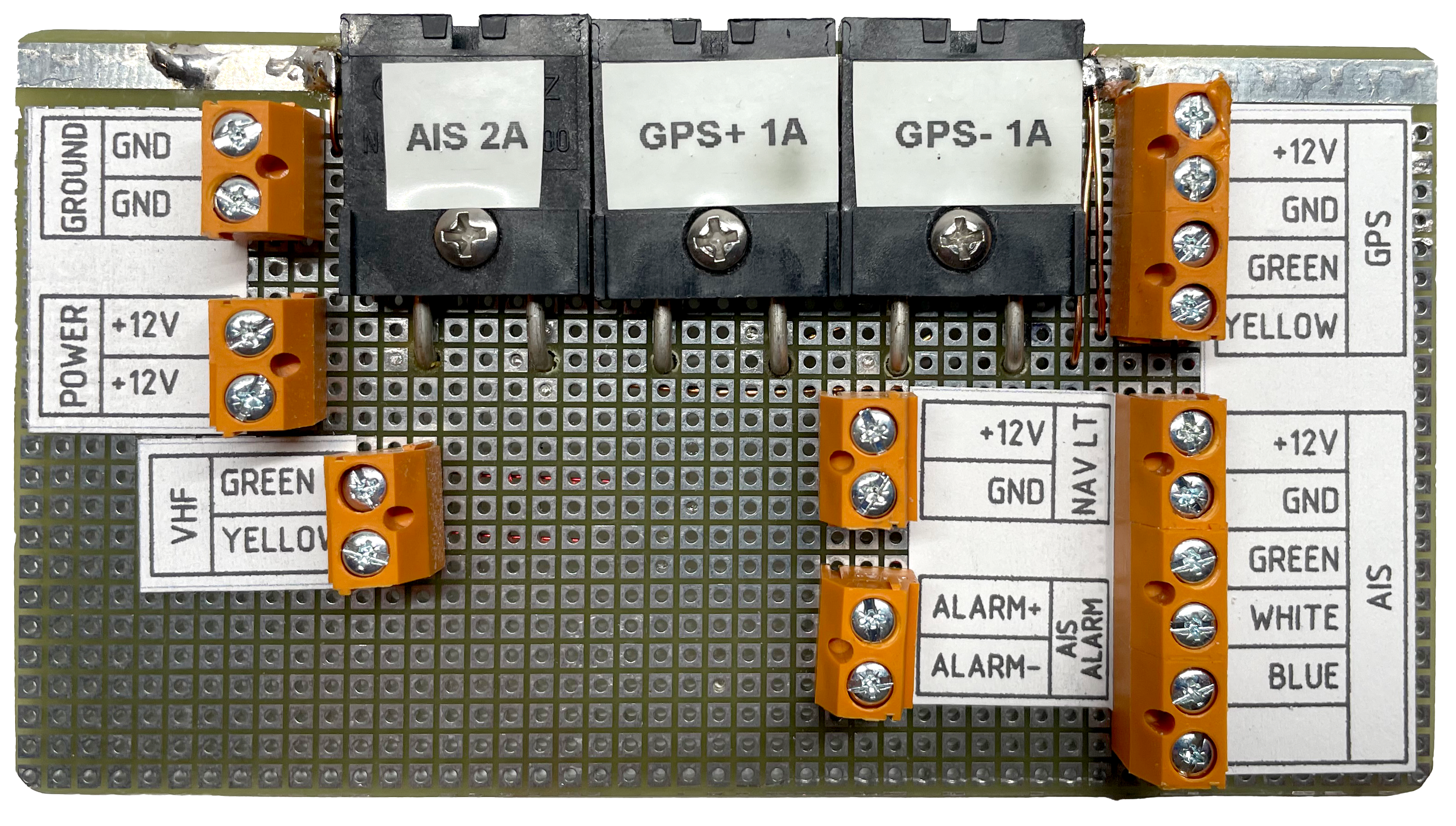
Under the nav station lid is a patch board for connecting together the wiring for the AIS, GPS, VHF, and nav station chart light. Here are the front side and the back sides (click the thumbnail photos to expand):

Bilge Pumps (LBP-Lower Bilge Pump, UBP-Upper Bilge Pump). Located under floorboard near engine inlet strainer.
| A-Screw | Circuit | B-Screw |
|---|---|---|
| Wire 38-R | TB1-1 | LBP-Brown |
| Breaker Switch | TB1-2 | LBP-Brown/White |
| Wire 38-B | TB1-3 | LBP-Black |
| Wire 39-B | TB1-4 | UBP-Black |
| Wire 39-R | TB1-5 | UBP bilge switch |
| Ś | TB1-6 | UBP-Brown/bilge switch |
Hamilton Ferris
Prop - plastic 8╝" x 5" three-bladed prop (OMC 386587, $50).
Diodes - 1N1200A 12A, Vf 0.95V @ 5A 25░C. Can be replaced with IR 63CPQ100, 100A, Vf 0.6V @ 5A 25░C
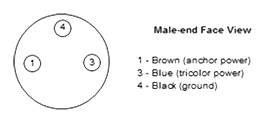
Orca Green Marine, model LXTA-P. This is an LED-based combo light at the top of the mast. Measured current @12V of 0.4A for either one being on. The anchor light turns off at sunrise with a built-in photocell in the green sector.
The light has a waterproof connector on the bottom. The mating cable is a Conxall Nano-Mizer 603ST2. The included cable has 24 AWG wires. The contacts are gold-plated.
My original unit failed with water intrusion. OGM replaced it under warranty 12/2008.
| ID | Color | AWG | Description |
|---|---|---|---|
| AP | R/B | 14 | Circuit breaker "Autopilot" to autopilot |
| B0 | B | 6 | Ground from battery charger to Link 2000 shunt |
| B1 | R | 6 | Positive from battery charger to House Bank |
| B2 | R | 6 | Positive from battery charger to Starting Battery |
| 10 | R | 8 | Starting Battery to fuse block FB2-3 |
| 11 | R | 8 | House Bank to fuse block |
| 12 | R | 10 | Fuse block to Battery Combiner "C" (Starting Battery) |
| 13 | R | 10 | Fuse block to Battery Combiner "A" (House Bank) |
| 14 | R | 10 | Battery Combiner Ground to Fuse block |
| 15 | R | 16 | Fuse block to ground on sense resistors |
| 16 | R | 6 | Circuit breaker "Radio" to SSB/VHF |
| 17 | B | 6 | SSB/VHF to Link 2000 ground shunt |
| 18 | B | 2/0 | Engine block to Link 2000 ground shunt |
| 19 | R | 2/0 | Positive from House Bank to distribution stud |
| 20 | B | 2/0 | Negative from House Bank to Link 2000 ground shunt |
| 21 | R | 2/0 | Starter bank + |
| 22 | B | 2/0 | Starter bank - |
| 23 | |||
| 24 | |||
| 25 | |||
| 26 | R/B | 16 | Power to fuse box for pumps |
| 27 | B | 2 | Lectra/San - |
| 28 | R | 2 | Lectra/San + |
| 29 | R | 2 | House + to Lectra/San circuit breaker |
| 30 | R/B | 16 | Anchor light |
| 31 | R/B | 16 | Steaming light |
| 33 | R/B | 16 | Deck lights |
| 34 | R/B | 10 | Tricolor |
| 35 | R/B | 12 | Lower navigation lights |
| 36 | P | 16 | Engine alarm connection |
| 37 | Br | 16 | Regulator power |
| 38 | R/B | 16 | Fuse box to lower bilge pump |
| 39 | R/B | 16 | Fuse box to upper bilge pump |
| 50 | R/B | 16 | Port cabin USB outlet |
| 51 | R/B | 10 | Inverter at nav station |
| 52 | R/B | 16 | Fuse box to propane sniffer |
| 60 | W/B/G | Water heater | |
| 61 | W/B/G | AC outlets | |
| 62 | W/B/G | Battery charger | |
| 71 | R | 16 | Spreader lightsŚmain mast |
| 72 | W/Bl | 16 | Spreader lightsŚmizzen mast |
| 73 | B/W | 16 | Instruments |
| 74 | R/B | 12 | Seawater pump |
| 75 | G | 10 | Cabin lights |
| 76 | W/B | 16 | Stereo |
| 77 | R/B | 16 | Fresh water pump |
| 78 | R/B | 10 | Accessory |
| 79 | G | 16 | Anchor light |
| 80 | W | 16 | Sump pump |
| 81 | Y | 16 | Bilge pumpŚlower |
| 82 | Gr | 16 | Steaming light |
| 83 | R | 16 | Instrument lights |
| 84 | R/B | 10 | Inverter under electrical panel |
| 85 | R | 6 | Fridge |
| 86 | R/B | 10 | Tricolor |
| 87 | W/B | 16 | Radar |
| 88 | R/B | 10 | Alternator voltage regulator power |
| 89 | R | 6 | +12V to electrical panel |
| 90 | R/B | 16 | Propane solenoid |
| 91 | R | 16 | Bilge pumpŚupper |
| ID | Color |
|---|---|
| B | Black |
| Bl | Blue |
| Br | Brown |
| Gr | Gray |
| G | Green |
| P | Purple |
| R | Red |
| W | White |
| Y | Yellow |
Green wires are for bonding. The 6 AWG wire is for lightning bonding and 8 AWG wire is for cathodic bonding.